Some test methods use a standard reference material to verify that a tester is functioning as intended during a weathering test method. Recently, a new lot of polystyrene material (referred to as “PS Lot 9”) has been approved for use as a standard reference material when running SAE J2527 (Automotive Exterior) and SAE J2412 (Automotive Interior). This material becomes more yellow over time; the amount of yellowing will indicate if the test is being performed correctly.
The use of PS is no longer mandatory in SAE J25257 or J2412. However, if one chooses to use this standard reference material, it should be done correctly. Here are some tips to keep in mind:
- Make sure the proper optical filter is installed in the tester SAE J2527 can be run using the Extended UV-Q/B filter or the Daylight-B/B filter, and SAE J2412 can only be run using the Extended UV-Q/B filter. Use of any other filter will affect the yellowing of PS Lot 9.
- Use the open-backed “mesh” specimen tray These test methods require use of the open-backed specimen tray. Using a solid back tray will affect the yellowing of the polystyrene material.
- Completely fill the tray with specimens or blank panels If large gaps are present in the open-backed specimen tray, that will affect the temperature profile of the test and will affect the yellowing of the polystyrene material.
- Mount the polystyrene in the “black panel” specimen holder The polystyrene material should always be mounted in a specimen holder without any backing, exposing it to air on both sides of the material. Additionally, it should be mounted next to the black panel temperature sensor in the tester.
- Always perform color measurements using a standard white tile as backing Polystyrene is a clear material and the evaluation of the test is affected by the color of the material behind the polystyrene. Always back the polystyrene with a white standard tile when taking color measurements.
Similar to specimen repositioning during a test, running PS Lot 9 in SAE J2527 and SAE J2412 is a best practice that laboratories should try and follow. But keep in mind that this material has only been tested for these two test methods, and the published limits should not be used when running any other test method.
Polystyrene is very sensitive to UV exposure as well as temperature, which is both good and bad for a reference material – tests can be performed quickly, but small changes in conditions can cause drastic changes on the outcome of the test. By following the tips above, this reference material can help you identify issues early in a test, saving you time and money.
In order to make use of polystyrene easier, we have created a tool you can use to see if your test is within limits. You can download it here.
If you want the certificate for the polystyrene with the limits in tabular form, you can find them here.
Automotive exterior testing has been using back spray for years. It’s required in order to run SAE J2527, the performance-based replacement for SAE J1960. This is the only standard that we know about which requires this odd function. Our Q‑SUN Xe-3 has this function; the Xe-2 does not. That leads one to wonder: does the back spray function accomplish anything? Is it useful?
The answer to both questions is an unequivocal NO. Furthermore, back spray is counterproductive, since it wastes a lot of water and can at times even wash off specimen labels.
The back spray requirement in SAE J2527 provides a great example of the perils of hardware-based weathering standards. The original tester used in developing this standard was improperly set up for this back spray “feature” over 25 years ago, and its implementation via a hardware-based standard forced everyone to propagate this error. As a result, today we’re stuck with a standard that uses more than twice the water it should, can only be run in certain testers, and does not produce better results than front spray or condensation test procedures.
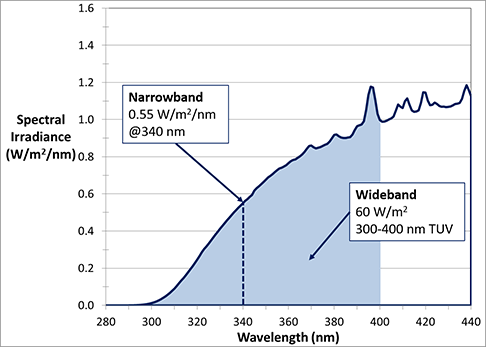
In Xenon and UV fluorescent accelerated weathering testing, an irradiance setpoint value is incomplete information without reference to the wavelength or wavelength range it represents. There are two classes of irradiance setpoints.
Narrowband irradiance setpoints include 340 nm and 420 nm, and represent a 1 nm wide bandpass, centered on the single wavelength value indicated (i.e. ½ nm on either side of 340 nm, for example). Narrowband irradiances use units of “Watts per square meter per nanometer.” This can be written as either W/(m2∙nm), W/m2/nm, or W∙m-2∙nm-1.
Wideband irradiance setpoints (usually “TUV” or “total UV”) are an integration of the irradiance from all wavelengths between two endpoints, usually 300-400 nm (accelerated laboratory) or 295-385 nm (outdoor). As a result, wideband irradiance values are generally much larger than narrowband irradiance values. Wideband irradiance is measured in “Watts per square meter,” written as W/m2 or W∙m-2.
The graph below is a spectral power distribution (SPD), which presents irradiance as a function of wavelength. This SPD shows that, for this particular light source, one could describe the irradiance either as having a narrowband irradiance of 0.35 W/m2/nm @ 340 nm, OR as a wideband irradiance of 40 W/m2 from 300-400 nm (TUV).
Weathering and lightfastness test standards typically specify an irradiance level as both a magnitude and the wavelength (or wavelength range) where it is controlled. Irradiance in fluorescent UV and xenon arc weathering testers can be controlled using narrowband or wideband setpoints.
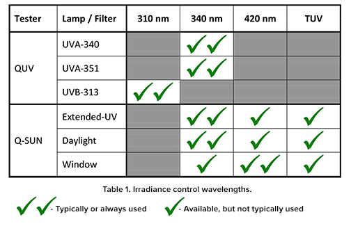
The selection of a narrowband control point in a QUV fluorescent UV tester is determined by the UV lamp type in use. For a Q-SUN xenon arc weathering tester, we suggest control using a wavelength or wavelength region in which the test specimen is sensitive. If the user is primarily concerned with color change, then a 420 nm control point is often used. If the primary area of concern is another type of physical property change, gloss loss for example, then a 340 nm control point is frequently used. A wideband TUV control point (300-400 nm) can be viewed as a compromise between the two narrowband (340 nm & 420 nm) control points, as it uses the total irradiance over the range 300 400 nm as its setpoint.
Selection of optical filters in a xenon arc tester also usually parallels this selection of irradiance control point. Typically, users testing with daylight optical filters use a 340 nm control point, while users of window glass optical filters generally use 420 nm control point. The available and most common selections for each lamp or filter type are presented in Table 1.
Polystyrene reference materials have been used in accelerated weathering test methods for decades to demonstrate acceptable maintenance and operation of weathering test chambers. Round-robin testing of these reference chips helped to establish acceptable lower and upper limits of polystyrene yellowing (Δb*) for SAE test methods J1885 (interior) and J1960 (exterior). However, since J1885 and J1960 were converted into performance-based standards (J2412 and J2527, respectively), the use of polystyrene reference materials in those standards is now non-mandatory. In line with this trend, polystyrene weathering reference materials are also no longer required by most automotive OEMs. Several factors have contributed to this change:
1. The factors causing yellowing of polystyrene chips may not be the same factors that degrade automotive materials in production today.
2. Some OEMs have developed their own reference materials, which better represent the materials critical to their products’ appearance and performance.
3. Modern weathering test chambers are capable of more precise control of test parameters, making tests more repeatable and reproducible without the need for validation from reference materials.
4. Availability of the current approved lot of polystyrene (Lot #8) has dwindled to near zero, and approval of a new lot of PS (Lot #9) has taken longer than anticipated to have proper limits established and to be brought to market.
5. The aging effects of polystyrene in storage are unknown.
6. Meeting the established requirements for polystyrene is often challenging, regardless of test apparatus.
Humidity is a general term that describes the amount of water vapor in the air. Humidity is a critical element of the outdoor environment and contributes to the material degradation in both weathering and corrosion. Humidity can be expressed as either an Absolute Humidity or a Relative Humidity (RH). Absolute humidity is the mass of water vapor in a given volume of air, expressed as g/m³. Relative Humidity (RH) represents the amount of water vapor in the air vs. how much it would contain if fully saturated, expressed as a percentage. Relative humidity is used much more commonly both in determining human comfort level and when describing natural and accelerated weathering.
Relative humidity can be measured a number of ways. Q-Lab uses two methods in our testers - electronic measurement with a digital hygrometer is used in Q-SUN xenon arc testers and mechanical measurement with a wet bulb/dry bulb hygrometer is used in Q-FOG corrosion test chambers.
Digital hygrometers are relatively common in everyday life. A digital hygrometer doesn’t require significant air flow, which makes it ideal for use in the Q-SUN tester and for ambient lab measurements. Digital hygrometers are readily available and simple to package.
A wet/dry bulb hygrometer uses thermometers, which makes it relatively easy to calibrate compared to a digital hygrometer. The wet/dry bulb requires a lot of air flow, which isn’t a problem in the Q-FOG tester’s blower module, and is also easy to maintain free from corrosion. Salt fog would degrade and eventually destroy a digital hygrometer if it were used in a Q-FOG chamber.
“Solar radiation” standards describe tests that are designed to characterize the performance of electronics subject to outdoor use or other harsh environments. The two most important solar radiation standards are MIL-STD-810G and IEC 60068 2 5. The Q-SUN product line can be used to meet these environmental “solar radiation” tests. A critical fact to note is that these standards are not specific test methods, despite having sections called “test methods.” Both standards spend considerable space discussing the concept of “tailoring”, which gives laboratories and engineers flexibility in designing tests that apply the environmental stresses discussed in each section. Thus not only are these standards performance-based in allowing multiple hardware designs, it is also possible to alter the actual test conditions if the result meets the general intent of the section. MIL-STD-810-G clearly states:
“It is important to note that this document does not impose design or test specifications. Rather, it describes the environmental tailoring process that results in realistic materiel designs and test methods based on materiel system performance requirements.”
MIL-STD-810-G and IEC 60068-2-5 both include numerous statements reinforcing this flexibility in selecting test conditions. In fact, the “solar radiation” tests in these standards are impossible to run in any chamber because they a table showing a target spectral power distribution from 280 to 3000 nm, that no artificial light source can meet. Because no single light source actually meets the specification, the user of the standard must apply sound and reasonable engineering principles to tailor the test by defining how the relevant environmental stresses will be applied. Q-Lab has prepared two special letters confirming that Q-SUN xenon-arc weathering testers can meet the performance requirements of Method 505.5 of standard MIL-STD-810G, provided that the document’s guidance on “test tailoring” is followed. Laboratories who need to add these standards to their scope of accreditation need to write a procedure that addresses specifically what test tailoring they have selected for their Q-SUN.
ISO 105 B04, “Colour Fastness to Artificial Weathering: Xenon Arc Fading Lamp Test,” is a standard practice designed to test outdoor lightfastness of textiles. Unlike most textile tests, this test uses water spray. Q-SUN accelerated xenon tester models Xe-2 and Xe-3 can both meet the conditions of ISO 105 B04. However, the optical filter configurations of these testers used to meet ISO 105 B04 are different, as shown in the table below:
| Tester |
Window-B04 Filter |
Window-B/SL Filter |
| Xe-2 |
Meets ISO 105 B04 |
Cannot Meet Temperature |
| Xe-3 |
N/A |
Meets ISO 105 B04 |
The reason for the difference stems from how the light exposure is defined in ISO 105 B04. Three separate sections of the standard specify use of 1) a xenon arc lamp, 2) a Daylight optical filter with “cut on” wavelength between 290-300 nm, and a3) heat filter that “steadily reduces” Infrared (IR) radiation. The heat filter is not precisely defined, but its intent is specifically noted as minimizing IR radiation to satisfy temperature conditions. An Xe-3 with Window – B/SL filter meets the irradiance and temperature conditions of ISO 105 B04 even without a heat filter and thus meets this standard.
In an Xe-2, the Window - B/SL filter results in insulated black panel (IBP, or “black standard”) temperatures outside the range specified by ISO 105 B04, so it can not be used to meet this standard. The Window - B04 optical filter lantern was designed specifically to meet the requirements of ISO 105 B04 in the Xe-2, and give the best match to historical user data from performing this test standard. If you are concerned with comparing test data in a Q-SUN to historic data collected in competitive tester, the best solution would be an Xe-2 with a Window - B04 lantern. Q-Lab also offers a special holder for mounting the blue wool reference material required by ISO 105 B04.
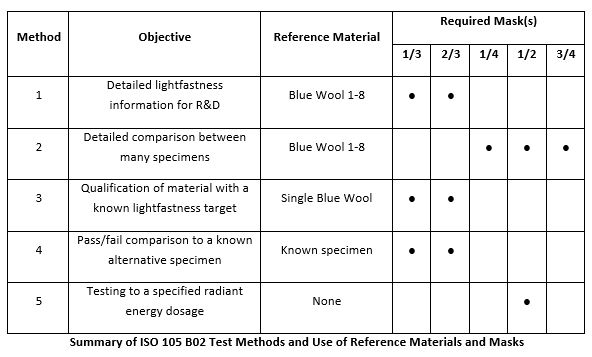
ISO 105 B02 is the most common lightfastness test for textiles worldwide. In this standard, a xenon-arc apparatus is used to expose test specimens and reference materials to light. The reference material consists of a set of eight bluish dyed wool pieces with UV/light durability ranging from low (Blue Wool #1) up to very high (Blue Wool #8). The performance of the test specimens is then compared to the performance of the reference materials to determine how “lightfast” the materials are. Five different exposure methods are described in ISO 105 B02 that vary in how they are set up and the information they generate. All of the methods use masks to cover a portion of the specimens to allow for easy visual assessment of the contrast between the area of the specimen that has been exposed to light and the unexposed area of the specimen (faded area vs. original area). The masks are shown in the photos below.
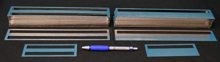
Textile Masks for Xe-2 (⅓ and ⅔)
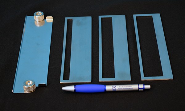
Textile Masks for Xe-3 (¼, ½, and ¾)
The table below outlines the five Exposure Methods in ISO 105 02 including why one would choose each method and what reference material and specimen mask(s) are required.
ISO 105 B02 is the world’s most widely-used textile lightfastness test. This standard was originally written before precise control of temperature and humidity was readily available in weathering testers, and like other standards it uses reference materials to compensate for this. ISO 105 B02 requires the use of a humidity test control fabric to verify chamber humidity during testing. This is a piece of wool dyed with a red azoic dye. The lightfastness performance of this fabric is largely dependent upon the humidity in the chamber. As the moisture content in the air increases, the lightfastness of this fabric decreases. By comparing the performance of this fabric to the
blue wool control material used in ISO 105 B02, one can approximate the humidity in the chamber using the following figure:
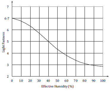 Blue Wool Lightfastness Rating of Humidity Test-Control Material v. Effective Humidity
How to Perform the Humidity Test
In order to perform the humidity test, you will need both blue wool reference material and the humidity test control fabric. The types of blue wool used in the test depend on which cycle you’re running:
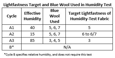
The humidity test control fabric and all of the appropriate blue wool reference materials are mounted on white cardstock and covered with a mask. The test is then run until the humidity-test control fabric achieves a grey scale of 4, and its performance is compared to the blue wool references. If the humidity-test control fabric has a similar performance to the blue wool indicated in the table above, then the tester meets the requirements and can be used to run ISO 105 B02.
Q-Lab’s accelerated weathering and corrosion testers all have some method(s) for measuring and controlling temperature, including black panel thermometers (BPT) and chamber air temperature (CAT) sensors. Reliable test results depend on accurate calibration of these devices.
Many of the sensors that measure and control temperature in Q-Lab weathering and corrosion testers can be calibrated using a standard reference thermometer and an insulated container of water. These devices include:
- Chamber air temperature (CAT) sensors in the Q-FOG, QCT, and (optionally) the Q-SUN Xe-1
- Black Panel (BP) thermometer in the QUV
- BP thermometer during heated immersion testing
- Wet bulb / dry bulb thermometers in the Q-FOG CRH
However, standard reference thermometers cannot be used to calibrate the temperature for an Uninsulated Black Panel (BP, also known as a Black Panel) or Insulated Black Panel (IBP, also known as a Black Standard) used in a Q-SUN xenon arc tester because they primarily receive their heat by absorbing radiant energy from ultraviolet (UV), visible, and infrared (IR) light and lose heat through convection to the chamber air. As a result, to be calibrated properly, therefore a Q-SUN BP or IBP must be compared to a special calibration thermometer – a UC202 or CT202 – that is itself a black panel sensor that has been calibrated to include the effects of radiant heat and convective cooling in air. This is not necessary for the sensors described in the previous section because chamber air sensors, and wet / dry bulb thermometers, are not exposed to any radiant heat from light sources.
QUV and Q-SUN accelerated weathering testers require the use of special calibration radiometers. The CR10 and UC10 are used for fluorescent UV lamps and the CR20 and UC20 are used for xenon lamps. These NIST-traceable devices ensure that the irradiance delivered to test specimens equals the irradiance called for in the user’s test method. Q-Lab’s lamps must be calibrated specifically with this radiometry equipment because of spectral mismatch between different UV fluorescent lamps or optical filters. Spectral mismatch is the effective difference in reading observed from an irradiance sensor when using a different spectrum than was used for calibration.
Q-Lab’s on-board and calibration irradiance sensors work using a photodiode, a semiconductor that converts absorbed photons into an electrical current. Since the photodiodes used in irradiance sensors only measure the intensity of light, but not the wavelength of light, filtering is used to make narrowband (310 nm, 340 nm, 420 nm), or wideband (TUV, 300-400 nm) irradiance measurements. If an on-board sensor is calibrated with a particular light spectrum, some error will be introduced when trying to measure irradiance using a different light spectrum.
For example, in a QUV, if you were to try and measure the irradiance of a UVB-313 lamp using a radiometer calibrated for use with a UVA-340 lamp, you would get an erroneous reading. A similar error would occur in a Q-SUN if trying to measure the irradiance at 340 nm with a Daylight-F filter using a radiometer calibrated for Window-Q. This is why it’s important to use the correct setting and device when calibrating a QUV or Q-SUN accelerated weathering tester.